How does a gear pump work?

Gears were already being used by the Assyrians and in ancient Egypt. It was not until the 9th century that this technology reached Europe, where it spread rapidly, was expanded to include gear pumps, and was ultimately used to pump liquids. In our case, we use this technique to convey hot-melt adhesive.
For the sake of completeness, it should be mentioned that a second conveying system, the piston pump, is also often used in the conveyer technology for hot glue. But we will talk about that in another blog post.
The basics of the gear pump
A gear pump consists of two gears arranged in a housing. These gears rotate in opposite directions, “capturing” the fluid that is trapped between them. The rotation of the gears transports the liquid and then passes it via a distributor to a hose or other application. This process enables a constant volume to be continuously delivered per unit of time.
The amount of liquid pumped depends on two main factors: the size of the pump and the speed of the motor that drives the gears. With the help of a frequency converter, the speed of the motor can be precisely controlled, which in turn regulates the delivery rate. As less liquid is often removed than the pump can deliver, a gear pump is often equipped with a bypass that directs the excess adhesive back into the tank.
The pressure generated in a gear pump depends on various factors, including the play of the gears in the housing and the viscosity of the fluid being pumped. For most applications it is necessary to reduce the pressure, typically to values between 10 and 60 bar. This is achieved by using various methods.
Pressure reduction in gear pumps
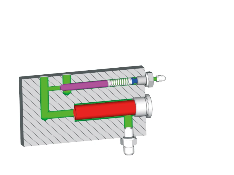
Bypass with compression spring: A common method for reducing pressure is to use a bypass with a compression spring. Here, the pressure generated by the gear pump is pressed against a piston that is held against a seat by a spring. The adhesive pressure can be regulated by adjusting the pre-tension of the spring by means of a screw. Higher pre-tension leads to higher pressure and vice versa. This enables customer-specific setting of the adhesive pressure.
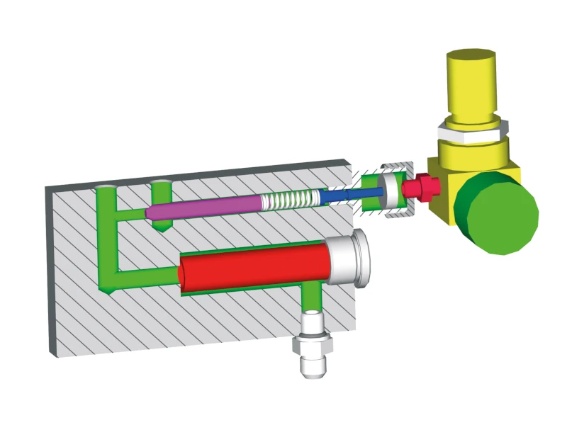
Pneumatic bypass: As an option for special applications, a bypass is available in which the spring is replaced by a pneumatic cylinder and a pneumatic pressure regulator. With this method, the delivery pressure can even be adjusted during the application, which is advantageous in certain applications, such as potting technology.
Advantages and disadvantages of gear pumps in melters
Gear pumps offer a number of advantages that make them attractive in many applications:
- Constant flow rate: This is particularly advantageous when applying adhesives, especially using the spray process.
- Adjustable delivery rate: The speed control allows the delivery rate to be adjusted, which is useful for small amounts of adhesive.
- Low pressure fluctuations: The pressure remains stable, which improves the quality of the application.
- Higher temperatures possible: Because fewer seals are required, higher temperatures can be processed, which is an advantage when using polyamides.
- High viscosity: Gear pumps can pump fluids with a higher viscosity of up to 70,000 mPas.
- Simple power supply: In some applications, such as bead application, only one power connection is required.
However, there are also some disadvantages:
- Circulation of excess adhesive: Some of the adhesive is unnecessarily recycled via the bypass.
- Adaption to changing quantities required: The system cannot automatically adapt to changing requirements.

- Our YouTube channel – knowledge to view - 6. Mai 2025
- Efficient adhesive supply with the granulate conveyor: How to optimise your production: - 15. April 2025
- Blocked hot-melt adhesive granules – causes, effects and solutions - 11. März 2025