Use of gear pumps to convey liquids
Gears were invented by the Assyrians and further developed in ancient Egypt. The technology only reached Europe in the 9th century. This system of power transmission spread quickly there and was later used, among other things, to convey liquids (and also adhesives).
The gear pump connected to an electric motor drive continuously delivers a constant volume per unit of time. The delivery rate depends on the size of the pump and the speed of the motor. The liquid adhesive is transported in the spaces between the teeth and the housing and then routed to the hose via a distributor.
How does a gear pump work?
When using a frequency converter, the speed of the motor can be regulated and thus also the delivery rate. As the amount of adhesive removed is often smaller than the delivery rate, a gear pump has a bypass that allows the excess adhesive to flow back into the tank. The maximum pressure generated by the pump is influenced by the play of the gears in the housing and the viscosity of the adhesive.
For most applications the pressure must be reduced. The usual pressures are between 10 and 60 bar. If the application quantity is to be maintained precisely with several application heads, tank systems with 2 to 4 motors are used. Precise application quantities per application head can then be set via the speed control of the motors.
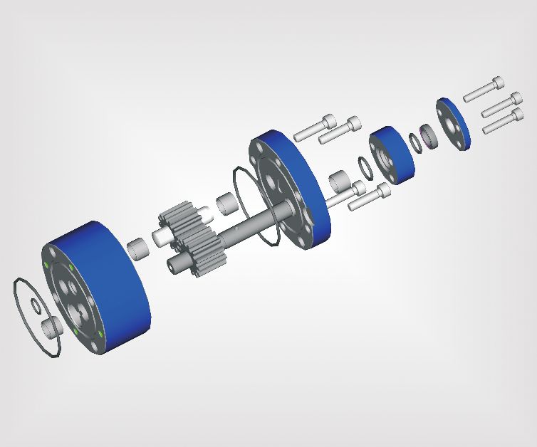
Figure 1: Structure of a HB 5010 gear pump
For most applications the pressure must be reduced. The usual pressures are between 10 and 60 bar. If the application quantity is to be maintained precisely with several application heads, tank systems with 2 to 4 motors are used. Precise application quantities per application head can then be set via the speed control of the motors.
Pressure reduction1: Bypass with compression spring
The delivery pressure in the system can be reduced very easily via the bypass. This acts like a safety valve. Tank systems usually have a bypass with compression spring as standard. Here, the pressure generated by the gear pump is applied against a piston, which is pressed against a seat by a spring. The pre-tension of the compression spring and thus the adhesive pressure can be adjusted by means of a screw. The higher the amount of adhesive removed, the higher the pre-tension of the compression spring should be. On the other hand, if the pre-tension is reduced, the adhesive can more easily overcome the resistance and flows back into the tank. The setting of the adhesive pressure is customer-specific.
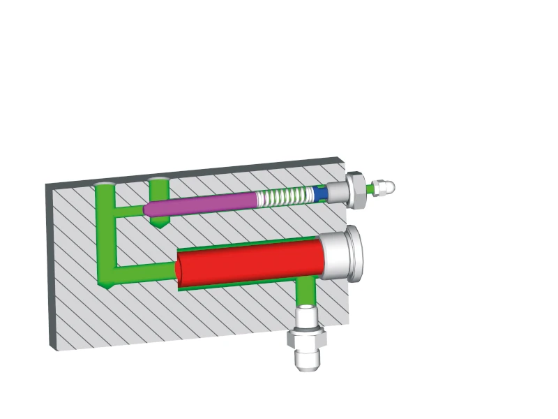
Figure 2: Bypass with compression spring
Pressure reduction 2: Pneumatic bypass
As an option for special applications, a bypass is available in which the spring is replaced by a pneumatic cylinder and a pneumatic pressure regulator. With this method, the delivery pressure can even be adjusted during the application, for example low pressure at the beginning and high delivery pressure at the end of an application. Such systems are used, among other things, in potting technology.
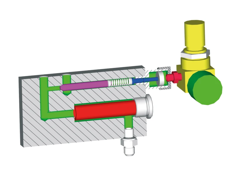
Figure 3: Pneumatic bypass
Advantages of an adhesive melting device with a gear pump
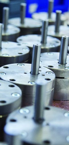
Figure 4: Component of HB 5010 gear pump
- Constant flow rate, advantage for spray application
- Delivery rate can be regulated by speed control, advantage with small amounts of adhesive
- Lower pressure fluctuations 8%
- Higher temperatures possible, as fewer seals required (advantage when using polyamides)
- High viscosity of up to 70,000 mPas possible
- Only one power supply required (for bead application)
Disadvantages of an adhesive melting device with a gear pump
- A portion of the adhesive is unnecessarily recycled via the bypass
- The system cannot automatically adapt to changing requirements